One thing at a time and two hands make light work!
Fellow scooters nuts and old friends Fleur and Mark were visiting Canberra. Mark, being at a loose end while Fleur worked, came around to lend a hand, which led to a productive day.
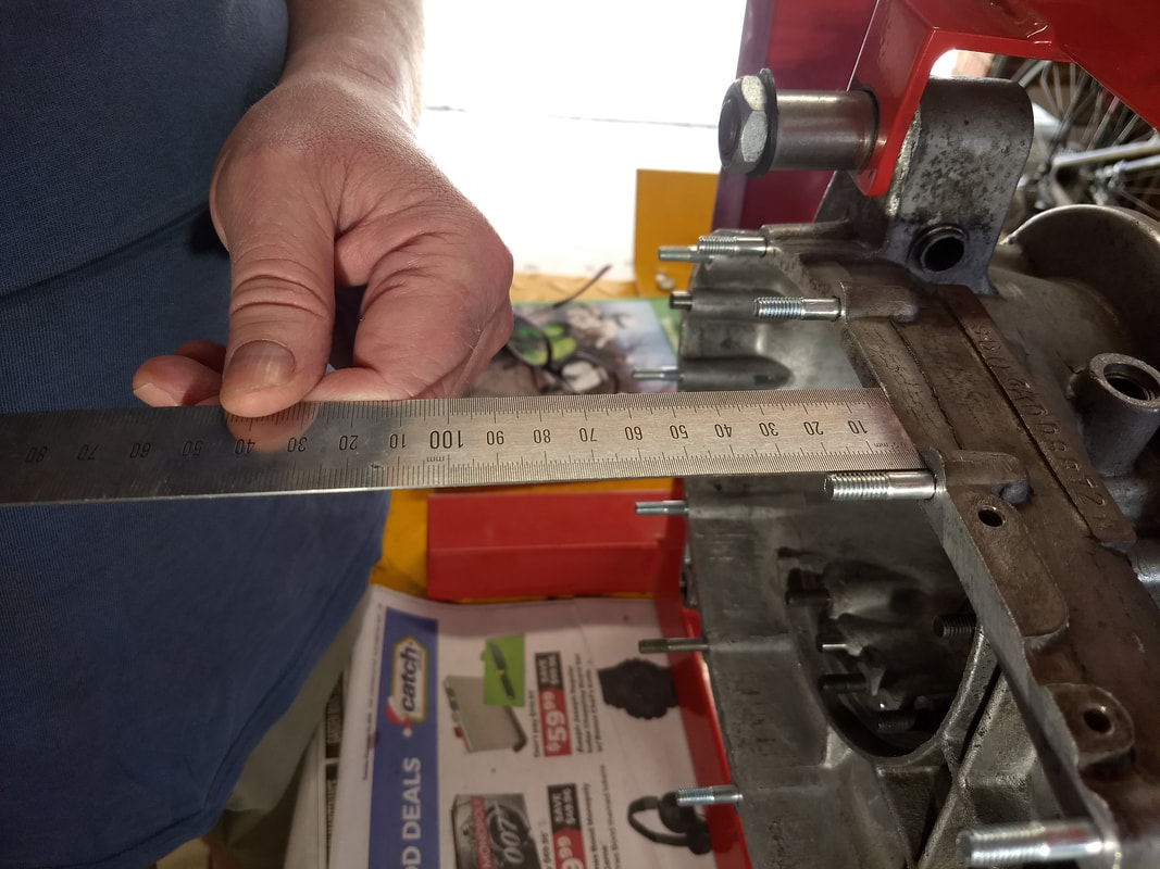
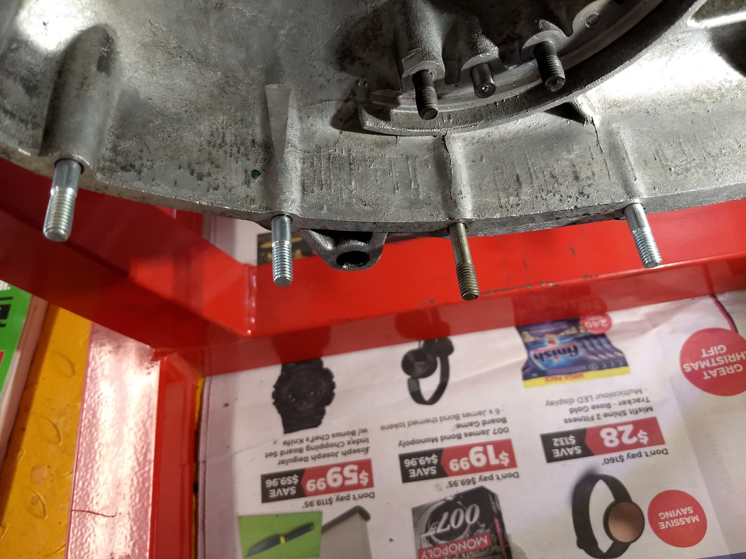
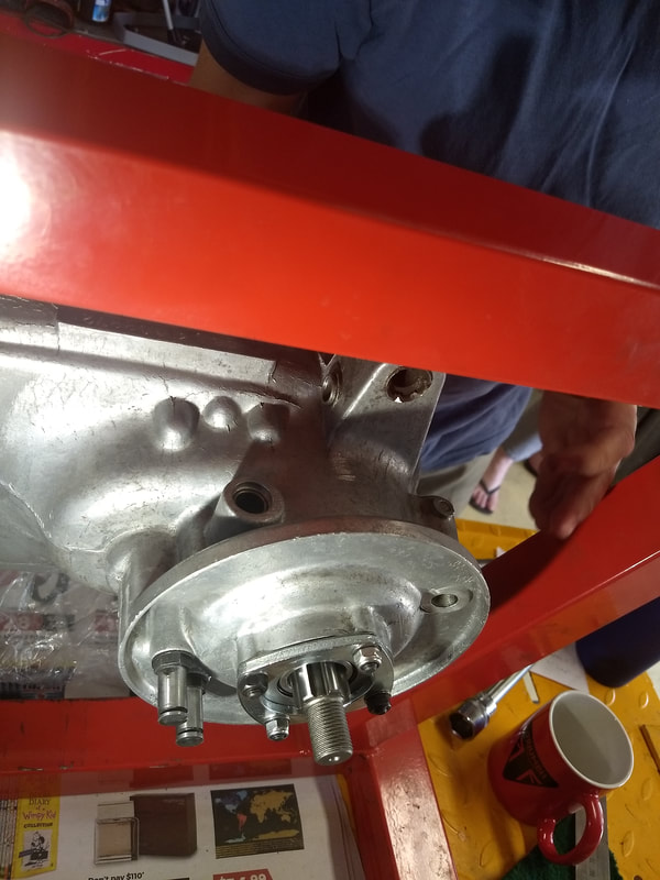
First up, checking the studs fitted yesterday. Sticky's manual recommends a minimum thread depth of 20mm and they all were over - result! Note, the longer and different coloured stud, which is fitted where the exhaust tail-pipe clamp gets bolted.
Fellow scooters nuts and old friends Fleur and Mark were visiting Canberra. Mark, being at a loose end while Fleur worked, came around to lend a hand, which led to a productive day.
First up, checking the studs fitted yesterday. Sticky's manual recommends a minimum thread depth of 20mm and they all were over - result! Note, the longer and different coloured stud, which is fitted where the exhaust tail-pipe clamp gets bolted.
 |  |
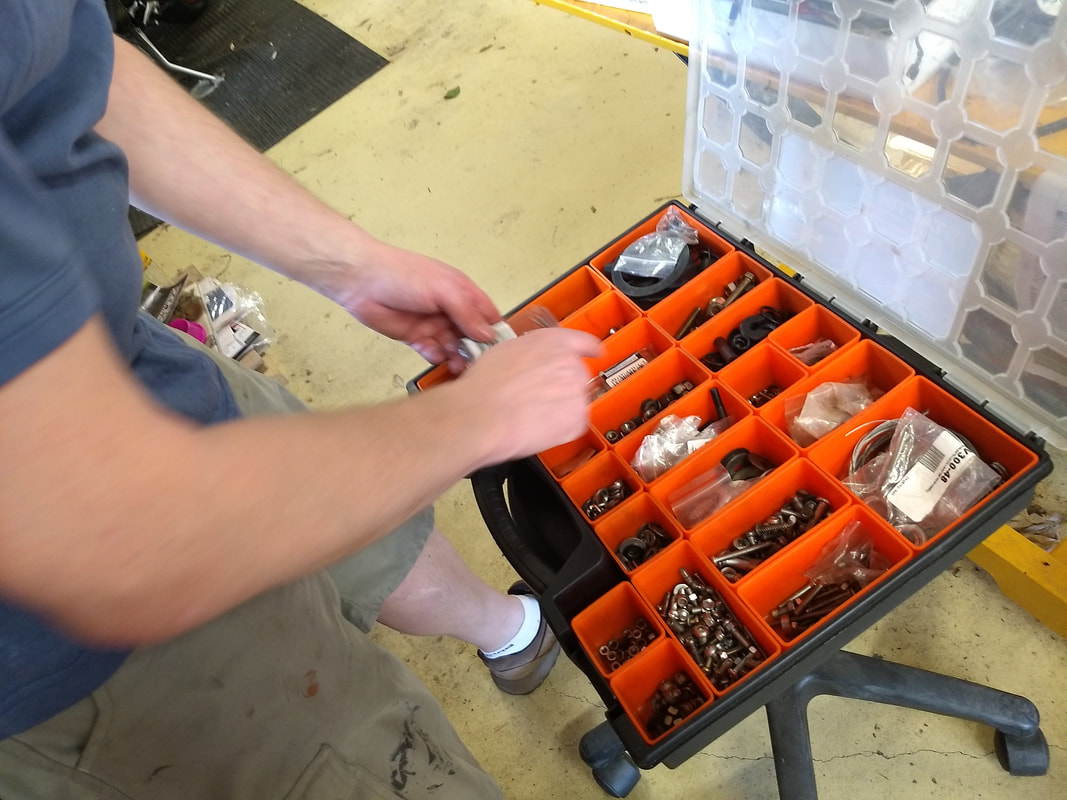
I'd checked and changed the engine mounts earlier. All club toolkits have silent block removal/replacement tools. Early purchases were these cheap versions. This one needed the chrome plating removing from the inside before it would work. We also had to replace the centre bolt after it had been used a few times. More expensive Casa Lambretta ones, supplied by Rimini Lambretta Centre, have now been included in many club toolkits. To use simply follow the instructions in Sticky's manual.

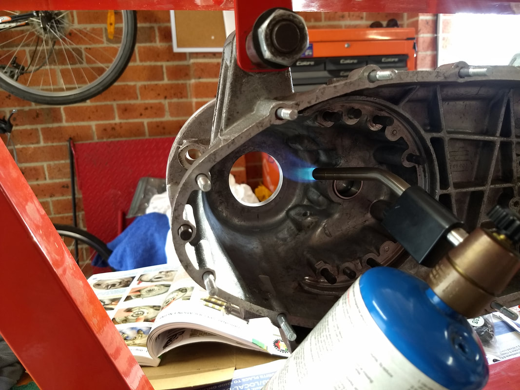
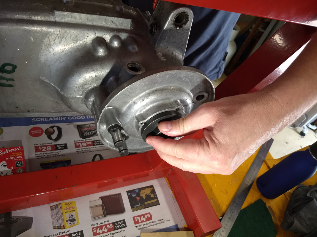
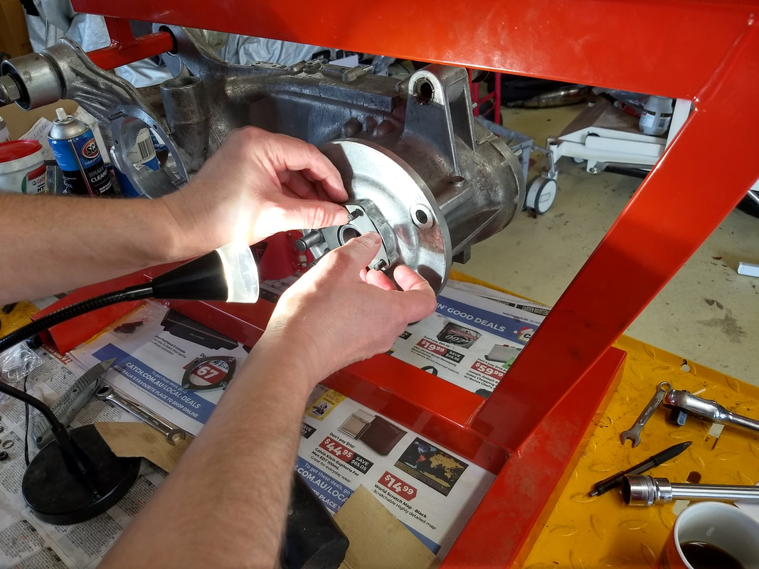
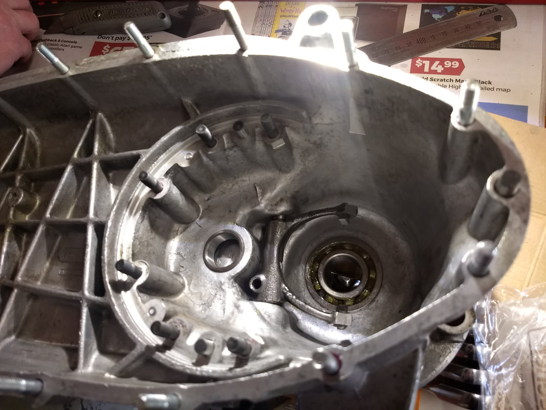
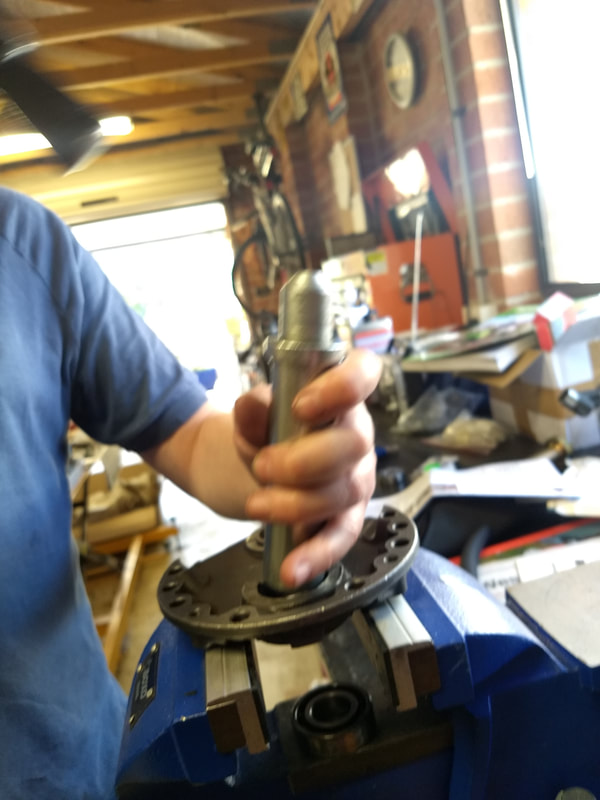
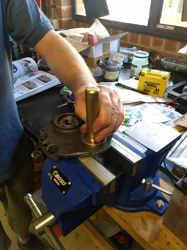
Now the fun begins. It's time to fit the rear hub bearing. I left Mark heating the casings while I went inside and put the new bearing in the freezer. AF recommend using a new double bearing, but this puts the rear wheel slightly out of line (or so some say). I went with a standard RIV Italian bearing, as supplied and recommended by Steve Diffey. After ten minutes in the freezer, this was packed with grease, the outside edges cleaned with parts cleaner and it went straight in to the heated casings with no force required. Note, Steve has since questioned why pack with grease, and I agree. This was in Sticky's manual, but using gearbox oil makes more sense. After all this is what it will run in.
 | 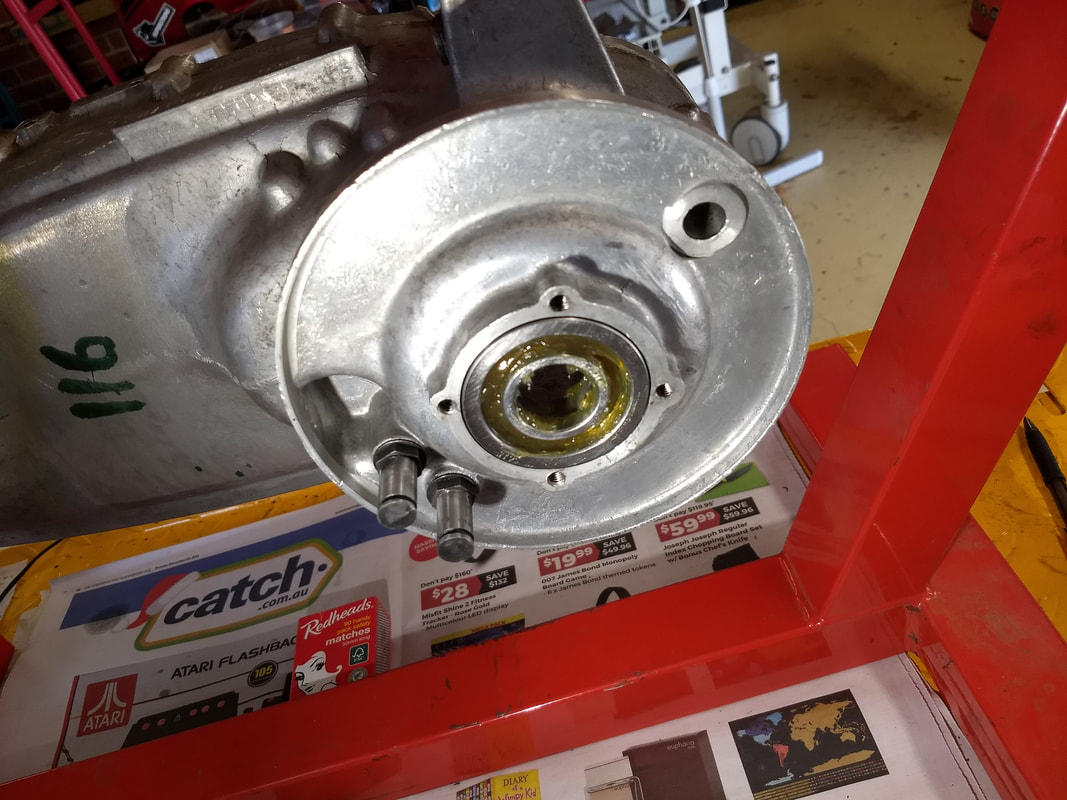 |
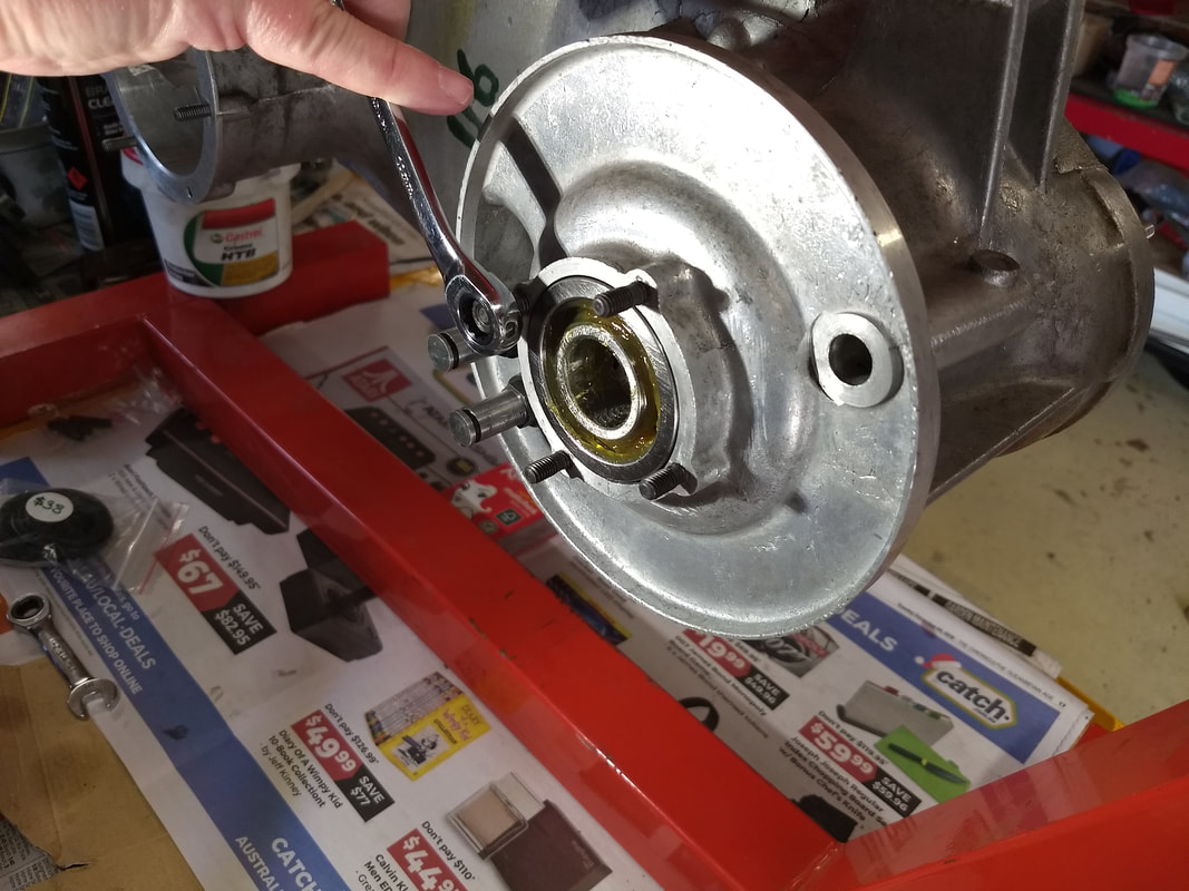
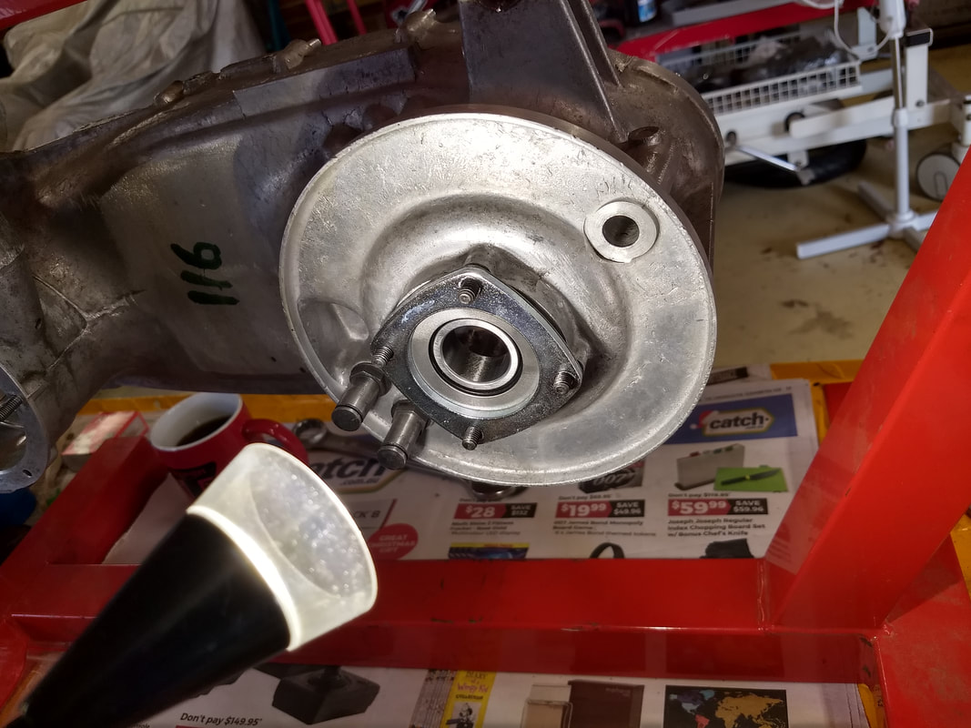
To be 100% sure it was seated right I checked it with a bearing puller. Yep, she's home!
The next job was to fit the oil seal studs. Once again these were double-nutted in to place with a dab of Loctite Stud Lock.
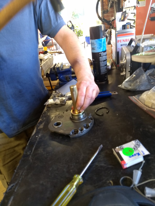
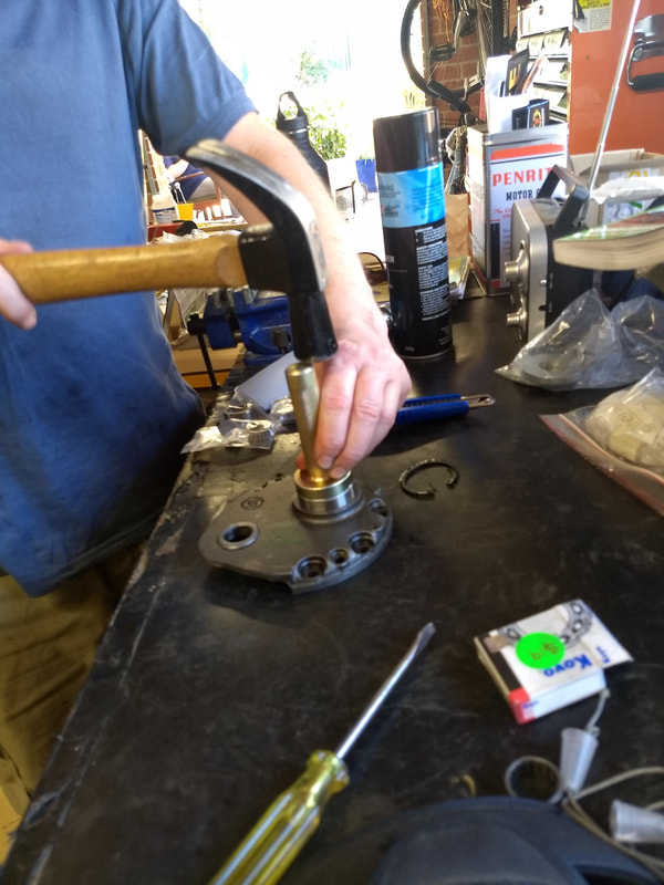
Then it was time to fit the oil seal. This wasn't too tricky, just needed the inner edge easing in to the bearing with a finger nail and tapping fully home with an oil seal drift. I've got one for fitting mag housing seals that was a good size to use.
 |  |
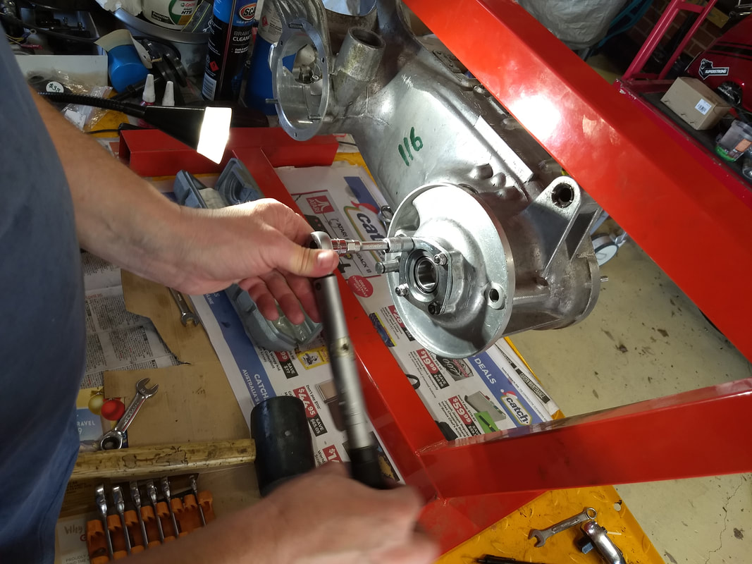
Now it's time to fit the oil seal spacer and flange. Flange. Love that word! Anyway, it's absolutely vital that the nuts are not overtightened, and the ABSOLUTE max torque setting to use is 4 foot-pounds, otherwise the flange will warp and the studs will bend. This has been the case on practically every Lambretta engine I've stripped. Due to the low torque setting, and the use of flat washers, I used Loctite on the threads and M6 Nyloc nuts (belt and braces). Well, I would have done, but I only had two! I've since been given more (thanks Nico at Motorini) and will use them for all four before the hub goes on, honest!
  |   |
Now the AF 5 speed gets unpacked and the much head scratching over the instructions ensues! Do I need to fit a shim on the layshaft before it goes in the bearing? Quick phone Paul Cain! He's busy but phones back, by which time we've worked out that you need to build the box once without any of the extra shims, then measure up and use them if needed! Paul confirms this is the case explaining all the slight differences between what should be standard sized layshafts and bearings! I'm now beginning to understand why all the 5-speed suppliers recommend that only competent mechanics fit them.
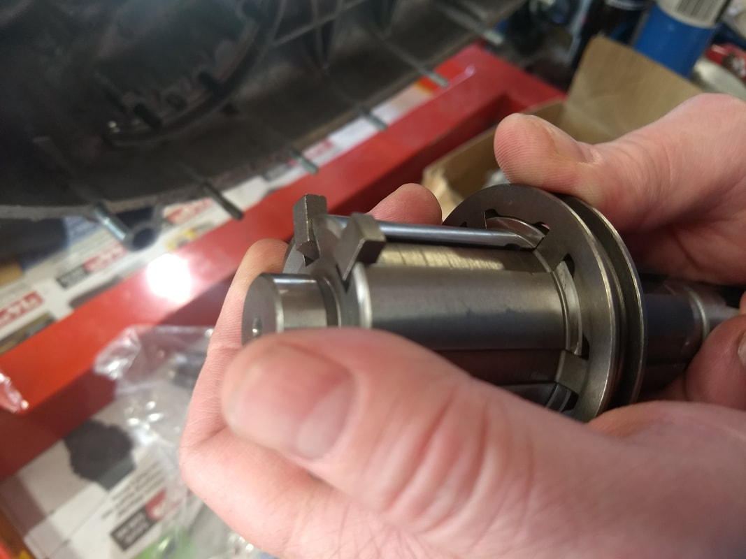
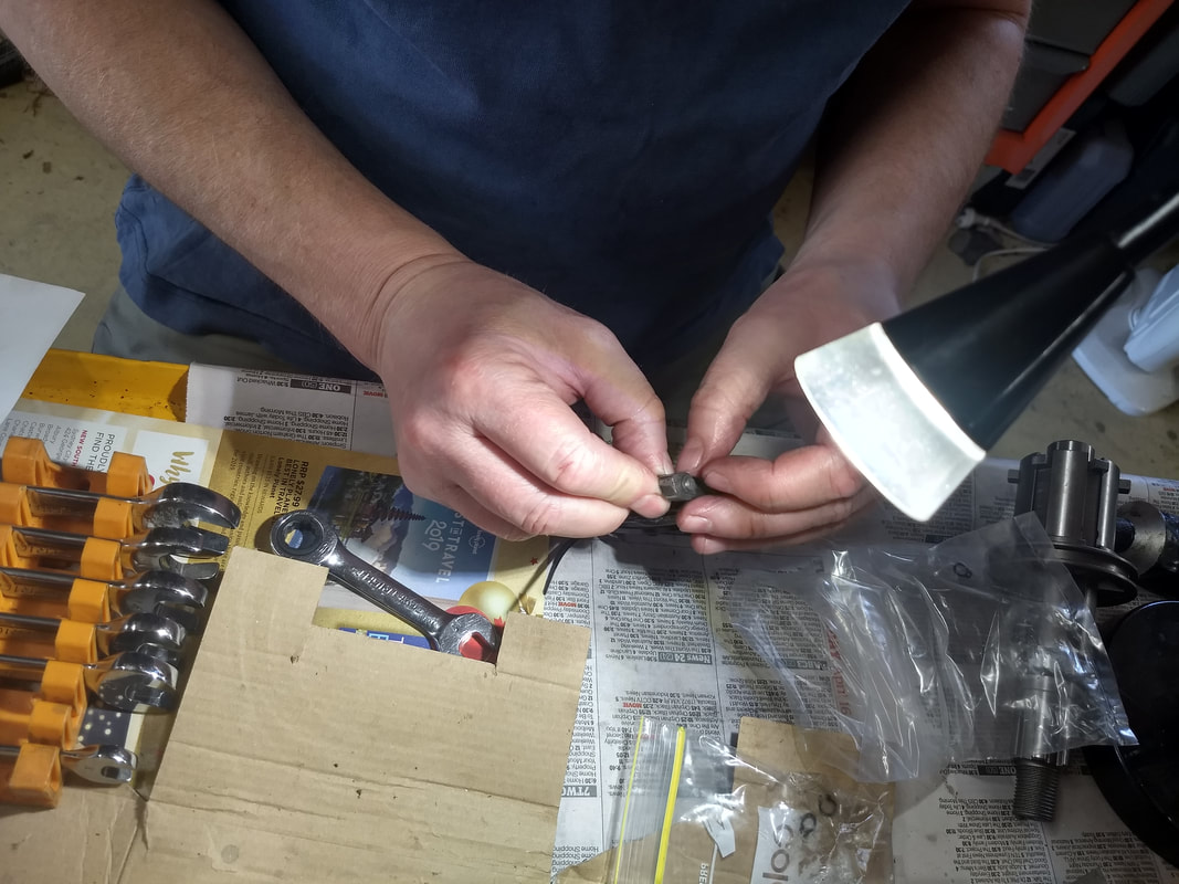
I wasn't 100% happy with the condition of the splines on the Indian layshaft when I stripped the motor. It would probably be fine, but with fitting a 5-speed box, new hub and tuned motor, I'd decided to order a new one from Steve Diffey. He supplied a FA Italia one, which are excellent apparently. The sliding dog from the five speed was then fitted to this. This involves juggling springs and balls, and bionic fingers. Needless to say we didn't only do it once!
I wasn't 100% happy with the condition of the splines on the Indian layshaft when I stripped the motor. It would probably be fine, but with fitting a 5-speed box, new hub and tuned motor, I'd decided to order a new one from Steve Diffey. He supplied a FA Italia one, which are excellent apparently. The sliding dog from the five speed was then fitted to this. This involves juggling springs and balls, and bionic fingers. Needless to say we didn't only do it once!
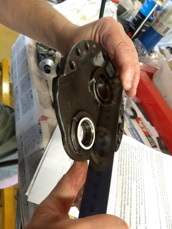
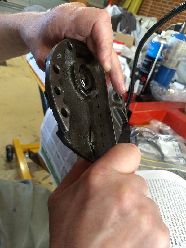
The AF kit instructions show some end-plate checks that I hadn't seen in Sticky's book, so these were carried out next. Basically the check is to see that the 6004 bearing face and the machined surface where the gear shim runs are parallel. Mine was good!
 |  |
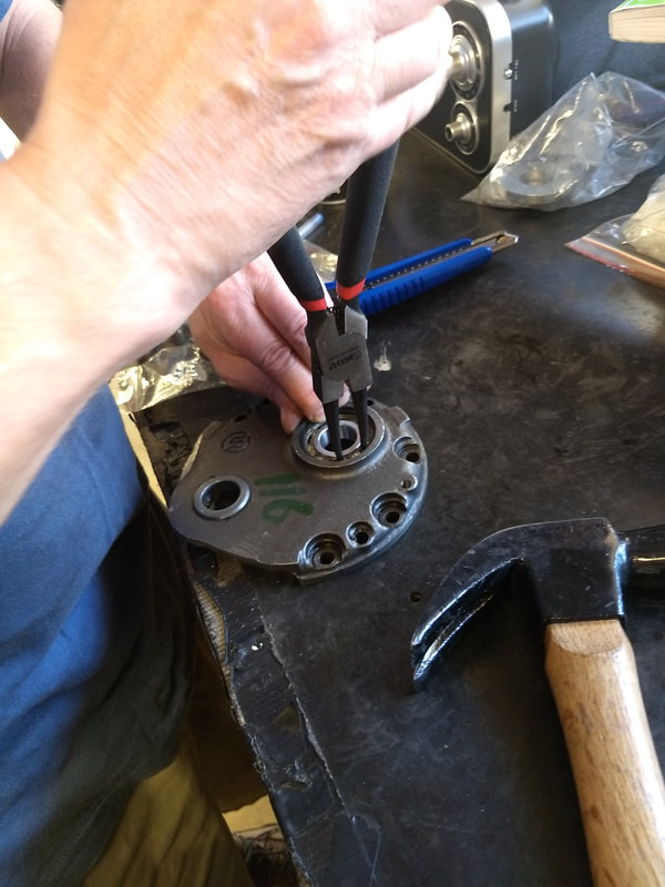
The kit came supplied with new gear selector pawls and circlips, so these were fitted next. Finger nails only required. I can never finger out how to use pliers on these tiny circlips!
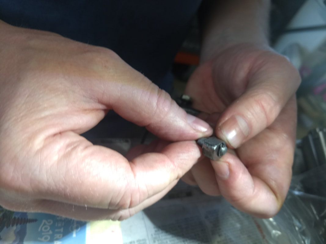 |  |
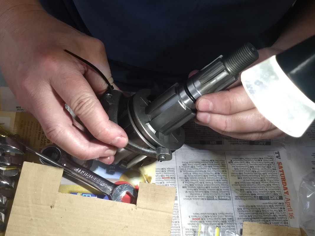
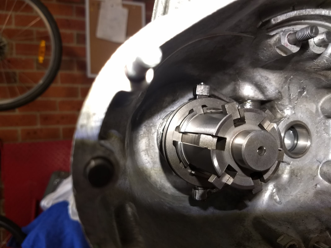
Once fitted the pawls appeared to work perfectly in the sliding dog. Yeah, things are going too well! Note the new O ring that has also been fitted to the layshaft.
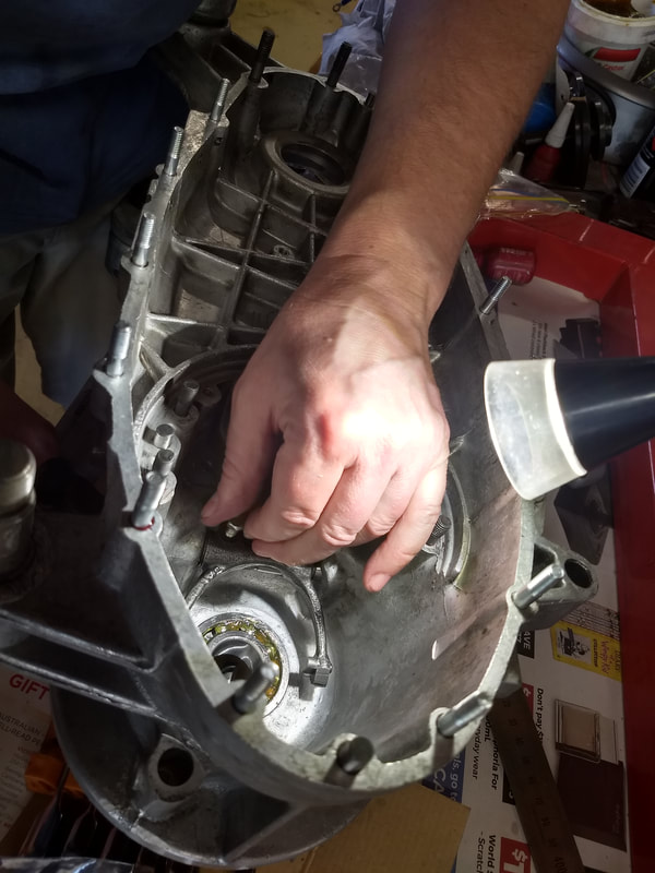
The selector fork has to be fitted in to the casings next. A new O ring is retrieved from the pack supplied by Steve, but then we realise that we have to drop the engine from the stand. The frame of the stand blocks us from inserting the selector rod. Only a minor annoyance but the first thing that hasn't gone like clockwork today. Following Sticky's instructions I'd centre-punched the rod and fork before removing, in theory meaning they can be put back in exactly the same position. Well it took some looking but we eventually found the punch mark...Also following Sticky's advice, and where an extra pair of hands was really useful, we made sure that the selector was bolted in place with no up and down movement, giving the tightest possible seal to prevent gear oil leaking.
 |  |
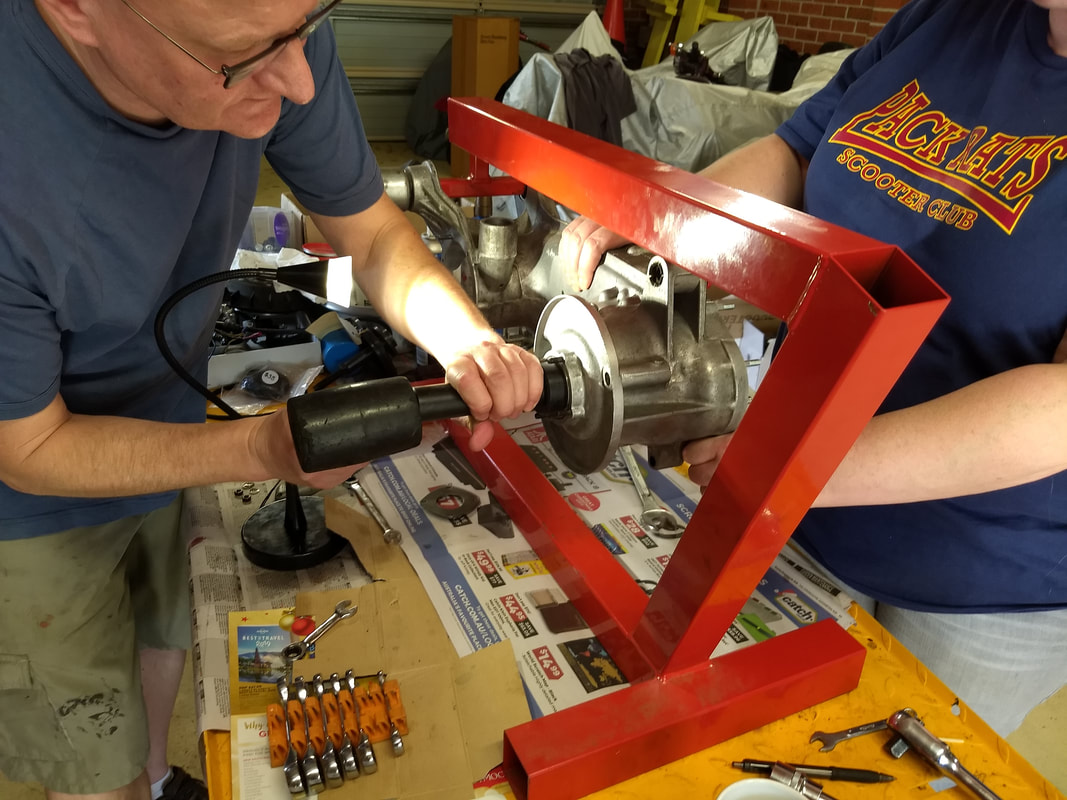
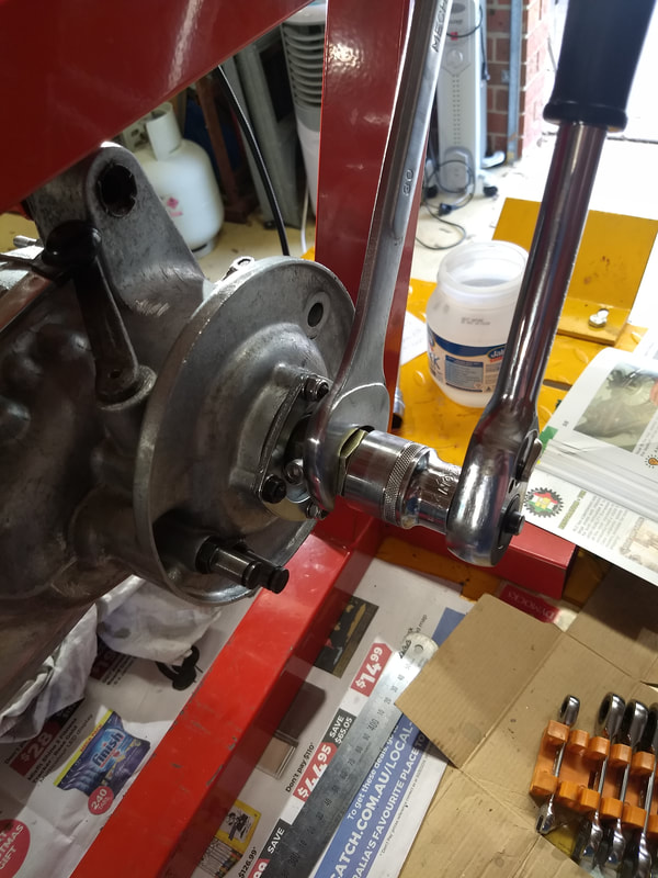
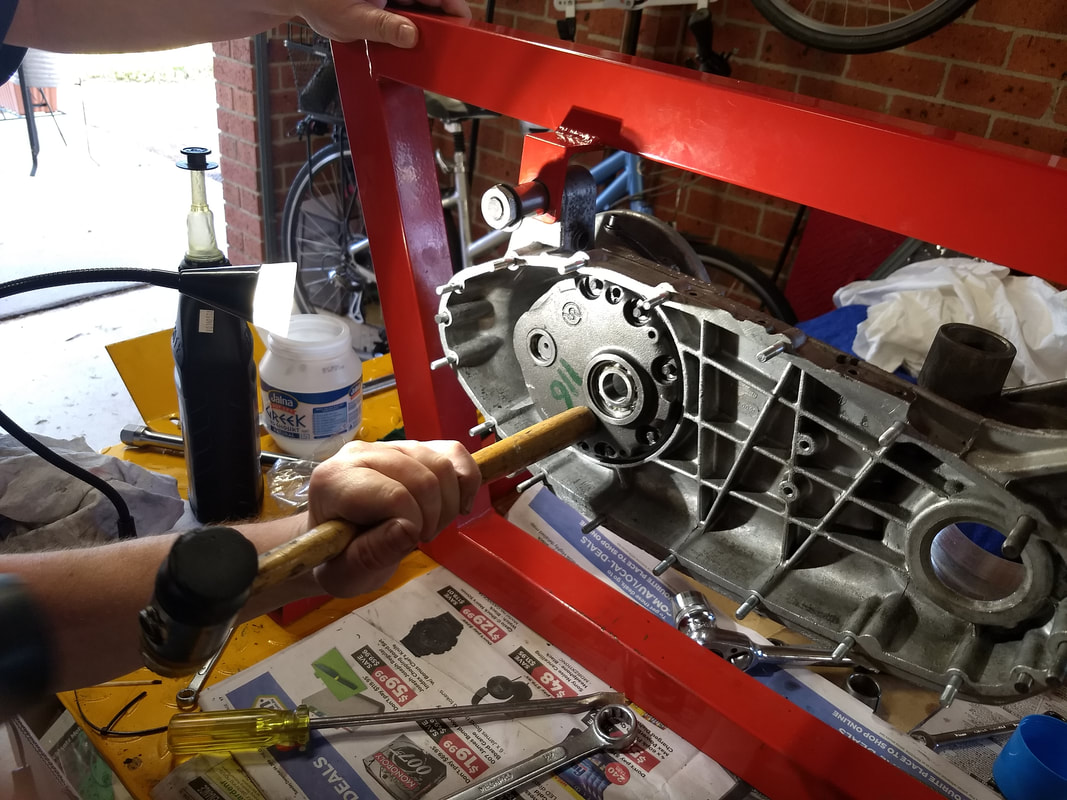
The new layshaft was a really tight fit in the bearing. Light tapping was not going to help, and I wasn't going to use any other sort of tapping on a bearing!
I'd bought one of the MB Scooters layshaft pulling tools, but the shaft wasn't through enough for the puller's nut to fit on the thread! A bit of head scratching and I came up with the idea of using the hub cone in place of the much longer sleeve from the tool. This worked, but only thanks to Mark being able to grip a cloth bound layshaft enough to stop it spinning while the nut was tightened! This got it in far enough to use the tool, which includes a captured bolt that sits in one of the splines to stop the shaft spinning. It still took two even with the tool, one to hold a spanner on the sleeve and one to use a wrench to wind the nut!
Finally the shaft was fully home, however it wasn't spinning freely! Closer inspection showed that the top leg of the selector fork was pressed hard against the sliding dog. Sticky does mention this and shows someone bending the arm with a screwdriver between it and the dog. It give this a quick go, but, well, it looked like it'd just bugger the bearing. My plan was to remove the whole selector and bend the leg in a vice, but Mark suggested using a ring spanner over the arm to do it still in place. This worked a treat, and after three "adjustments" the layshaft spins smoothly and the selector slides lovely!
The next step in the AF instructions is to check the neutral position of the selector arm. Well bugger me if the arm isn't about 130 degrees out! Looks like we hadn't found the correct centre punch mark when fitting. The whole selector arm has to come out, the sliding dog needs removing, meaning the springs and balls need refitting...At this point photo taking was forgotten as we; removed the selector, found the correct punch mark, fitted the selector again, and somehow managed to refit the dog, springs and balls with the layshaft still in place. This last bit needed several attempts, a tap from the trademark Lambretta persuading mallet and a trip inside for a Bandaid… Finally the arm was in nearly the position shown in the AF instructions.
All five gears positions were selectable, but, to be sure, I fitted the tie-rod and gear arm brackets, using a trunnion to connect it all up. I wanted to make sure that nothing would stop all five gears being selected with all the gobbins in place! Sure enough there was one arm position where fifth seemed a bit dodgy, and one where first seemed a bit close. We spent a while unbolting the selector arm, carefully moving it one notch on the spline. Is that better or worse? We also tried some brand new Scootopia controls in place of the original Indian ones, which for whatever reason I had laying around. In the end we both agreed on the original position, the other one looking like an impossible angle for the cables to move the arm from fifth. Selecting first still moved the arm very close to the front bolt on the bracket, but Mark suggested that using an allen bolt in place of the hex head would give more clearance, and I was happy with that. Whatever happens I don't want to have to strip the whole engine down again due a problem found when cabling up! Worst case an after market set of controls might be required.
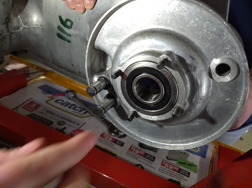
Moving on and it was time to replace the 6004 bearing and layshaft bearing track in the endplate. The old 6004 bearing was whacked out. I'd bought the proper drift for fitting the new one, in anticipation of this job, and fitting was quick and simple. Money well spent...
Moving on and it was time to replace the 6004 bearing and layshaft bearing track in the endplate. The old 6004 bearing was whacked out. I'd bought the proper drift for fitting the new one, in anticipation of this job, and fitting was quick and simple. Money well spent...
  |   |
Steve had supplied a sealed bearing, so I rang him to see if I should remove the seals. While discussing this he mentioned a potential problem with the selector fork hitting the back of the engine casing, preventing fifth being fully selected, even though it looks like it's working. All good until riding for the first time when it jumps out of fifth! Checking this and I'm definitely fully selecting fifth with clearance between the selector arm and casings after the positive click in to fifth gear position. Phew. Still it's so good to be able to phone the dealers here in Oz and get this sort of advice on the spot. Both Paul and Steve have been phoned today, and both provided excellent hints and tips. I know the other superdealers will also do the same.
Next, change the layshaft bearing track. The 6004 drift worked great for this job as well.
Next, change the layshaft bearing track. The 6004 drift worked great for this job as well.
At this point Mark was phoned by Fleur. Finally she's finished work and they can start the long drive back to Sydney. Thanks Mark. I made amazing progress today thanks to your help and suggestions! Two heads were definitely needed at times.
The AF instructions suggest fitting the layshaft bearing and end-plate at this point, to see that the layshaft still spins freely. So I do this and it does, which is nice.
The AF instructions suggest fitting the layshaft bearing and end-plate at this point, to see that the layshaft still spins freely. So I do this and it does, which is nice.
Unfortunately it looks like first is no longer fully selected, the selector dog possibly touching the plate! Now I decide to call it a day, and have a beer before putting my tools away. I really should have done that, but halfway through the beer I decide to remove the end-plate and then stop. Oh dear, somehow the plate goes wonky while being removed and the threads on one of the new studs get porked in the process.
Like that last run on the snowboard, that last round of schnapps, that last fandango, just don't do it!
YOU ALWAYS FUCK UP THAT ONE LAST LITTLE THING...
Like that last run on the snowboard, that last round of schnapps, that last fandango, just don't do it!
YOU ALWAYS FUCK UP THAT ONE LAST LITTLE THING...
 RSS Feed